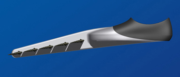
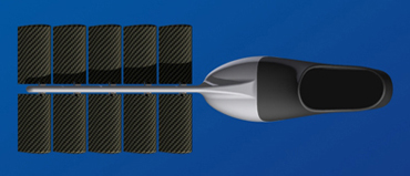
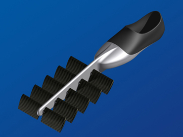
Operating principle
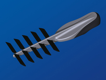
As you can see it on the drawings below, the fin is made of a succession of small wings.
These wings can swivel freely around their axis, up to a certain angle, a stop preventing them from being turned over completely.
Comparison with a traditional fin :
The following representation makes it possible to visualize the forces exerted on a traditional fin, on the left, and on a
fin with wings, on the right :
- the red arrows and red zones materialize the positive forces for the advance of the swimmer ;
- the blue arrows and blue zones, the negative forces ;
- the five light blue lines materialize the instantaneous trajectory of the displacement of the fins. It is common
with the two fins to facilitate the comparison. We can thus imagine that two swimmers are advancing at the same speed and having
the same rhythm of finning.
The traditional fin is represented in its most powerful phase of finning. This phase takes place for generally only approximately 1/4 of the complete cycle.
Another phase of push exists, when the leg goes up, but it is less efficient. It is also during this 1/4 of cycle that the ankle undergoes more
constraints because it is in full extension.
The fin with wings, on the other hand, is in an unspecified phase, as it is in the 3/4 of the cycle of finning. (Wings being,
tilted "head in top" when the leg goes up)
This difference will allow the swimmer having a fin with wings to exert his traction more regularly, and on a time
definitely longer. Besides the performance profit which results from this, the comfort of the ankle is largely improved.
Moreover, we see clearly on the drawing of the traditional fin that one part of the surface of it generates a neutral or opposite
force within the direction of advance.
On the other hand, for the fin with wings, the totality of the produced forces are directed forwards.
Lastly, the distribution of the forces on a traditional fin is directly connected to its curve.
If a swimmer uses a fin which is not hard enough compared to its physical force, it will fold exaggeratedly. Admittedly,
the forces will be directed more favorably (red arrows more directed forwards), but they will be especially weaker.
The output will be then reduced. Conversely, a too hard fin will not fold enough and the forces will only be directed very little forwards.
For the fin with wings, whether the swimmer forces little or much, the wings will be always favorably tilted. There is no limit
because the wings positioning varies according to the speed of the swimmer.
The operation of the wing of the fin being based on the same principle as a wing of plane, it is necessary, before going further, to have
a minimum of knowledge in aerodynamics and aeronautics...
Small reminders of aerodynamics :
When the wing of a plane is inclined, the flow of air around this one is done more quickly on the top than on the lower part.
Particles of air being presented at the beginning of the wing have a larger distance to traverse in order to arrive at the end. This difference in speed
will generate a difference in pressure from a side to the other, thus creating an ascending force.
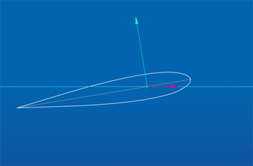
You can see this phenomenon on the figure below. It is about a cross-section of a wing (its profile) in action. The moving
plane from right to left :
- the white curves materialize the flow of the particles of air arriving on the wing;
- the light blue line represents the trajectory of the wing;
- the colored curves, located mainly on the front, are isobars (lines connecting all points at the same pressure).
Red representing the high pressures and blue the low pressures, with, as explanation, colors presented on the small graph on right-hand side ;
(The blue on the top and red on the lower part zones, materialize the flow along the wing.)

Roughly, the isobars of the lower part are red, indicating high pressures, and those of the top are mainly green-yellow, indicating lower pressures.
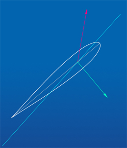
The forces which result from it can be materialized such as on the following figure :
- the red arrows represent the pressures, and the dark blue ones the depressions ;
- the clear blue line materializes the trajectory of the wing ;
- the yellow arrow represents the force of push of the plane (provided by the engines) ;
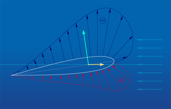
By adding all these small forces we obtain one force resulting, here materialized by the green arrow. This force is exerted
in a point called the center of pressure, and is always perpendicular to the cord (line connecting the front to the back of the wing).
These forces are directly related to the profile of the wing, and are not fixed. They evolve according to the slope of the wing.
To see what occurs when the wing is inclined, turn back to click on animation higher. That will enable you to note the evolution of the isobars.
If there is any modification of the pressures, there is some modification of the forces and thus the center of pressure also will be modified.
![]()
The more the wing is inclined and the more the center of pressure moves back.
All that was described above, in the air, is directly applicable in the water. The only major difference being that water is approximately
830 times denser than the air. The forces will be thus much more important.
Comparison plane/fin with wings :
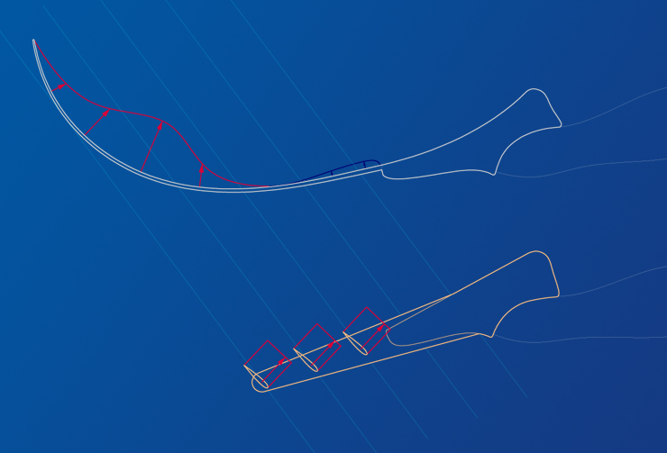
On the level of the trajectories :
The diagram below compares the trajectory of a wing of plane and a wing of the fin of a swimmer when both (plane and swimmer)
advance on straight line at constant speed :
- the wing of the fin is next to the reference mark (2); that of the plane to the reference mark (1) ;
- the purple one corresponds to the trajectory of the swimmer or of the plane ;
- the light blue one represents the respective trajectories of the wings.
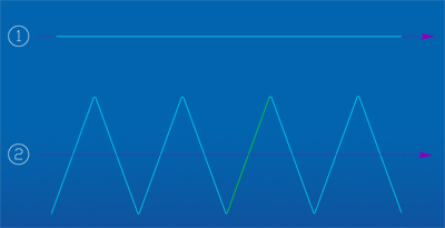
The trajectories of the plane and its wing are confused whereas the trajectory of the wing of the fin "zigzag"
on both sides of that of the swimmer.
On the level of the forces :
Let us consider a fin of test whose wings would be fixed in the most favorable position to be only used on the green zone of the preceding diagram.
The forces which would be exerted, in comparison with those of a wing of plane, are represented in the following figures :
- the wing of the fin is represented on the right side ;
- the red arrows represent the force of traction, the green ones those of reaction (force resulting, applied to the center of
pressure and described above) ;
- the two light blue lines materialize the respective trajectories of the wings.
The plane generating a force of traction on the wing with an aim of rising, the force of reaction must thus be directed upwards.
This is true when the wing is more tilted than its trajectory (as that is represented on the drawing).
For the fin, we requires that the force of reaction be directed forwards (to advance the swimmer). With this intention, it is
necessary that the wing must be less tilted than its trajectory.
If we want that our fin of test could be used on the whole trajectory represented on the diagram (and not, only the green zone), it should
be modified. We can, for example, fix the wing on an axis in order to this which can turn freely.
Then, we add a stop making it possible to stop its rotation in the exact position of the diagram above (for the rising phase),
and another one for the position opposite (for the downward phase). This fin would then have an ideal efficiency for the whole of
the trajectory. What corresponds to one speed of travel of the swimmer .
Evolution :
The speed of a swimmer being practically never constant, it is necessary to go even further.
A swimmer, finning and accelerating gradually, would induce the following trajectory :
(To improve the visibility, the trajectory was cut into two and only the most interesting parts were preserved.)
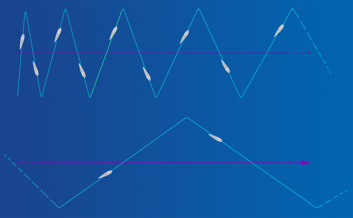
With this trajectory, our fin of test with stops would have only one optimal zone of operation, materialized again in green.
So that a wing has an ideal efficiency whatever the speed of the swimmer, it is necessary that it positions as that is materialized
in gray on the diagram above. It is necessary that its slope stays constant compared to its trajectory. This for each half-period
of the finning.
To arrive at that, the wing will be fixed on the axis, slightly behind center of pressure.
This principle is represented on the figure below :
- the red points represent the center of the axis ;
- the red arrows, the force of traction exerted by the foot ;
- the green points, the center of pressure ;
- the green arrows, the force of reaction ;
- the light blue lines, the trajectory of the wing ;
- the gray lines, the cord of the wing (prolonged at its two ends).
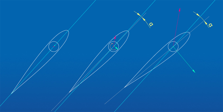
On the left, the wing is "at rest" no force is in action and we slightly see the materialization of the point of
traction (center of the axis) behind the center of pressure.
In the medium, it is about a wing at the beginning of its displacement, in rising phase of the finning. It is inclined little by relevance at its trajectory, the center of pressure is thus still in front of the axis.
The two forces being exerted in opposed directions, that will generate a rotation of the wing, materialized by the orange arrow.
The angle of inclination "α" will increase, inducing a move back of the center of pressure.
When the center of pressure is confused with the center of the axis (dot of traction), rotation stops.
This position of balance is represented on the drawing on right-hand side.
At the time of the downward phase, the phenomenon is reversed. The slope of the wing is thus constant compared to the trajectory of the wing,
in each of the two phases of the finning.
The angle "α" with balance depends on the form of the wing (its profile) and the positioning of the center of the axis on the wing. The more the axis is behind,
the more the angle of inclination will be high. This is true so far the disconnection limit of the wing.
A last element to be taken into account is that the wings of the same fin are all independent from each other.
Their “absolute” slope (slope, not compared to their trajectory but, for example, compared to the bottom of the
swimming pool) is function of their own trajectory. The wings close to the foot will be thus less tilted than those of the end of the fin.
Indeed, for the same speed of advance they undergo an oscillation of weaker width.
Try of a dynamic representation of the forces :
The following video dynamically represents the evolution of the forces at the time of a cycle of finning (a rising phase and downward one).
For a better comprehension :
- the movement of the fin is not represented (the body remains fixed), but only the movement of the wings and of the flow of water ;
- the part of the wing located after the end of the axis is made transparent ;
- the two arrows of force were moved in-depth (only) until the end of the axis. Actually the blue one would be in the middle of the
axis (thus hidden in the body) and the red one roughly in the middle of the wing (thus a little nearer to the body)
The virtual swimmer who animates the fin moves from left to right and its frequency of finning is constant.
For better apprehending the various movements, it is preferable to be focused on a part at the same time :
- First of all, the dark blue arrow which represents the force of reaction.
It is at its maximum when the wing is in position of balance, then it decreases as the force of traction decreases.
Lastly, it becomes quasi null during the inversion of the movement of finning, then it reverses for the second phase.
It is always perpendicular to the cord of the wing.
we can also notice the migration of the center of pressure ( dark blue arrow bases),
which is in front of the center of the axis at rest, then is merged with the one in position of balance.
- Then, the red arrow, which represents the force of traction due to the movement of the foot. It is independent of the
others, and passes simply from one side to the other.
- Lastly, the green arrow, which roughly materializes the rate of travel of the wing, and its trajectory.
we can see that the rotation generated by the imbalance of the forces is stopped when the wing arrives at a certain slope.
The wing cannot exceed this position because if the slope increases, the center of pressure is behind the axis and the
direction of rotation is then reversed, bringing back the wing in its position of balance.


All that this site contains cannot be used without the agreement of the owner.
- Palmaile the fin with wings -